

Electric Grid Modeling for Distribution Generation Applications
2012 M.Eng. thesis, McGill University
Written by Michael Nicholas George
Chapter 2:
Characteristics of Typical Distribution Feeders
2.1 - Characterization and Classification
Distribution systems vary among geographic areas. The biggest differences in topology and operational philosophies are between systems in North America and those in Europe. These differences are related to grounding configuration, the share of lines comprised by the primary and secondary levels of the distribution system, phasing, and nominal frequency (50 Hz vs. 60 Hz systems).
In Canada, distribution systems are classified into three distinct categories – urban, suburban, and rural. These categories are distinguishable by their voltage levels, topology, loading, and protection scheme. Table 2-1 highlights these characteristics. Distribution feeders can be further classified into overhead and underground feeders, depending on the type of layout used. Overhead feeders are typically used for rural distribution, while underground construction is more common in high-density urban systems.
Table 2-1: General features of different distribution system types

Rural feeders have a number of features that distinguish them from the urban and suburban types. Because they serve a relatively large geographical area, their topologies feature long backbones with a large number of laterals. Because power is traditionally delivered over a greater length of overhead lines, higher voltage levels are used in order to mitigate losses. The associated voltage drop in these long lines is typically compensated by at least one in-line voltage regulator. The geographical vastness and the sparseness of loads of such feeders justify the design and operational differences in such feeders.
Because of the fundamental differences between each type of distribution system, the benchmark feeders generated by the methodology presented in this thesis will be confined to rural feeders consisting of overhead lines in a radial layout. Rural feeders are suitable candidates for DG integration for several reasons. Many DG’s are located at sites away from major population centers in order to avoid problems with pollution (in the case of fuel-burning microturbines) or noise pollution (in the case of wind turbines). Additionally, reclosing protective devices are found exclusively on rural overhead feeders and pose a risk to DG out-of-phase reclosing in the case of a temporary fault and temporary island scenario. Because rural feeders are typically radial and do not redundant service paths during contingencies, DG integration provides a great deal of potential improvement in the reliability of service provided to customers. For these reasons, rural feeders will be the focus of these benchmarking efforts.
2.2 - Elements of a Distribution Feeder
Most rural feeders can be described by a set of components that is universal to this type of feeder arrangement. Table 2-2 lists these components, as well as the parameters that are essential to describing them for the benchmarking work. This framework derives from that used in describing urban and suburban distribution systems for their respective benchmarks. This set of components will form a template from which parameters and other details can be obtained to complete an appropriately descriptive benchmark for the rural feeder in this paper.
Chapter 5 describes the rural feeder that serves as a case study for this benchmarking work. The feeder is described in terms similar to the template outlined in Table 2-2.
Table 2-2: Elements Common in Rural Feeders

2.3 - Uses of a Distribution Feeder
Of fundamental consideration in selecting a benchmark model for a given distribution feeder is the type of studies it is to be used for and, more specifically, the timescale of interest for the study. Table 2-3 lists some of the different types of studies used when assessing DG interconnection options, distinguishing them by the time range over which they are most useful.
The timescale is also an important factor in determining the degree of modeling complexity necessary for the benchmark and its components. For example, in steady state, it may be more appropriate to model loads not as a fixed complex power injection but rather as a value that fluctuates over time in the form of a daily load profile. Likewise, in transient analysis addressing electromechanical types of transients, the effects of temporary or permanent switching actions of the protective devices are more visible and relevant, calling importance to how these devices are modeled over this time range.
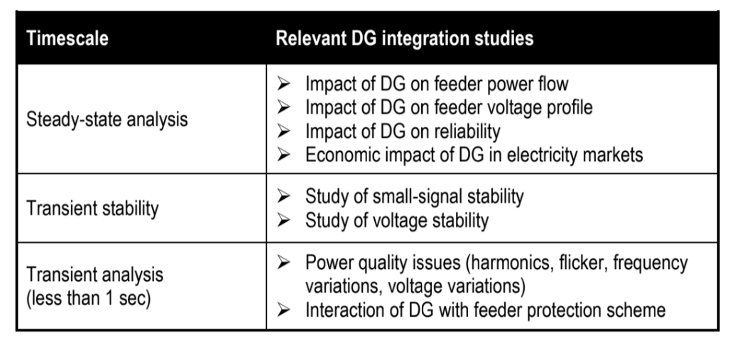
Table 2-3: DG Interconnection Studies
2.4 - Obtaining a Representative Distribution Feeder Benchmark
One of the goals of this work is to represent the benchmark feeder in EMTP for transient analysis. The data available for this feeder benchmark comes in the form of a DSAP model, which is a portrayal of the distribution feeder for purposes of planning and steady-state operation studies. Each load and each line section are represented individually, comprising a feeder model of hundreds of components. There is very little practicality in transferring this data directly into EMTP and trying to execute a detailed, nonlinear simulation with hundreds of these components. A feeder reduction technique is sought in order to yield a simpler network that will require less computational effort and data for repetitive “what-if” sorts of DG impact studies.
2.5 - Applicability of Benchmarks
The potential value of the feeder reduction methodology described below is that it may provide some guidance towards obtaining a simple distribution feeder from a larger one encountered in reality. This simplified feeder would be used for DG impact studies of the type mentioned above. Some guidance is also provided for the eventuality in which data is missing.